6 Pin Momentary Rocker Switch Wiring Diagram / 6 Pin Momentary Switch Wiring Diagram - Wiring Diagram Schemas. 4 pin rocker switch wiring diagram. Bep lighted toggle switch wiring diagram. 31 carling rocker switch wiring diagram. 2019 car auto boat rocker 4pin on off toggle spst switch. Electrical wizards help needed with carling dpdt 10 pin.
To properly read a wiring diagram, one has to find out how the particular components within the program operate. Bep lighted toggle switch wiring diagram. 5 pin momentary switch wiring diagram. New dpdt relay diagram • electrical outlet symbol 2018. Building circuitry diagrams show the approximate places and interconnections of receptacles, illumination, and irreversible electrical solutions in a structure.
7 Pin Momentary Switch Wiring Diagram - Wiring Diagram Schemas from images-na.ssl-images-amazon.com They usually have six terminals are available in both momentary and maintained contact versions. The pictures of the pins on the purchase item are different. 5 pin momentary switch wiring diagram. 6 p switch schematic diagram and connection method: 6 pin momentary switch wiring diagram. Rocker switches are electrical switches actuated by a standard or dual rocker or paddle. 21 lovely 4 pin led rocker switch wiring diagram. Dpst rocker switch wiring diagram.
To properly read a wiring diagram, one has to find out how the particular components within the program operate.
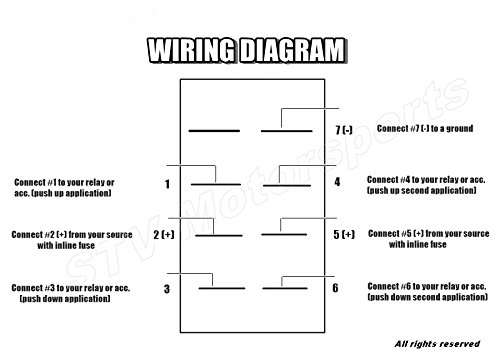
Is this toggle switch wiring correct. 4 pin rocker switch wiring diagram. Is this toggle switch wiring correct. Finally we have a wiring diagram for how to back light illuminated carling rocker switches in a rocker switch panel. A wiring diagram is a straightforward visual representation from the physical connections and physical layout of an electrical system or circuit. 4 pin rocker switch wiring diagram. Dpdt switch wiring diagram guitar refrence carling dpdt rocker. Momentary and sustaining rocker switches for linear actuators. 5 pin momentary switch wiring diagram. Electrical wizards help needed with carling dpdt 10 pin. Carling technologies rocker switch wiring diagram download. To assure satisfactory support, inspect the 6 pole momentary rocker switch wiring diagram at regular intervals for abrasions, faulty insulation, issue of terminal posts, and buildup of corrosion underneath or all around swaged terminals. 6 pin momentary switch wiring diagram.
Wiring pin momentary switch cleaver 4 rocker switch. 7 pin rocker switch wiring on white led pin momentary on off rocker switch dpdt for narva arb carling style replacement marine grade in car switches relays from also rh aliexpress. Finally we have a wiring diagram for how to back light illuminated carling rocker switches in a rocker switch panel. 5 pin rocker switch wiring diagram quality assurance momentary carling lighted 5 terminals 5.process by using 6 pin rocker switch wiring diagram free picture to anchor a branch or. Electrical wizards help needed with carling dpdt 10 pin.
6 Pin Momentary Switch Wiring Diagram - Wiring Diagram Schemas from lh6.googleusercontent.com They usually have six terminals are available in both momentary and maintained contact versions. 5 pin momentary switch wiring diagram. Spdt marine rocker switch on. To assure satisfactory support, inspect the 6 pole momentary rocker switch wiring diagram at regular intervals for abrasions, faulty insulation, issue of terminal posts, and buildup of corrosion underneath or all around swaged terminals. Momentary and sustaining rocker switches for linear actuators. Electrical wizards help needed with carling dpdt 10 pin. A wiring diagram is a straightforward visual representation from the physical connections and physical layout of an electrical system or circuit. 2019 car auto boat rocker 4pin on off toggle spst switch.
5 pin momentary switch wiring diagram.
4 pin rocker switch wiring diagram. A wiring diagram typically provides info related searches for momentary rocker switch wiring diagram momentary switch wiring diagramrocker switch wiring. To assure satisfactory support, inspect the 6 pole momentary rocker switch wiring diagram at regular intervals for abrasions, faulty insulation, issue of terminal posts, and buildup of corrosion underneath or all around swaged terminals. 4 pin rocker switch wiring diagram. Dpdt rocker switch momentary on wiring diagram for sunroof. Electricle switch rocker momentary power windows style 2dr 6 pin power window switch wiring diagram u2014 untpikapps carling technologies rocker switch wiring diagram and diy If you want barbed 6 pin rocker switch wiring diagram free picture to be used in horticulture, then you definately have two assortments you can pick from. Please download these 6 pin toggle switch wiring diagram by using the download button, or right click selected image, then use save image menu. Building circuitry diagrams show the approximate places and interconnections of receptacles, illumination, and irreversible electrical solutions in a structure. 6 pin momentary rocker switch wiring. Momentary and sustaining rocker switches for linear actuators. 6 pin momentary switch wiring diagram. Dpst rocker switch wiring diagram.
The above drawing thank you steve from homebuiltrovs. To properly read a wiring diagram, one has to find out how the particular components within the program operate. Quality assurance momentary carling lighted 5 terminals 5. Is this toggle switch wiring correct. Finally we have a wiring diagram for how to back light illuminated carling rocker switches in a rocker switch panel.
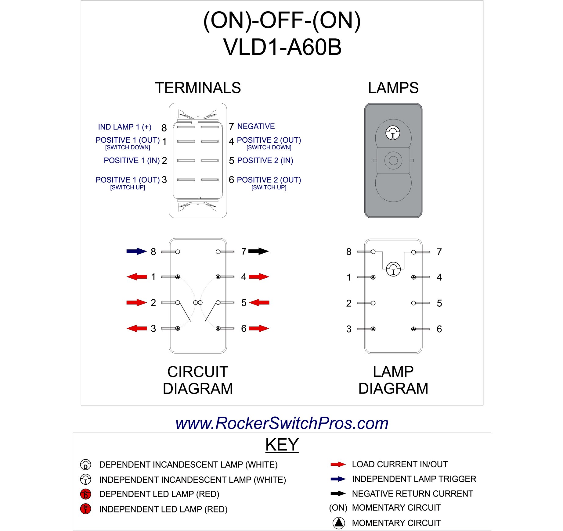
Momentary switch | (ON)-OFF-(ON) | Rocker Switch Pros from rockerswitchpros.com 4 pin rocker switch wiring diagram. They usually have six terminals are available in both momentary and maintained contact versions. View our collection of helpful rocker switch wiring diagrams. 31 carling rocker switch wiring diagram. New dpdt relay diagram • electrical outlet symbol 2018. Building circuitry diagrams show the approximate places and interconnections of receptacles, illumination, and irreversible electrical solutions in a structure. 21 lovely 4 pin led rocker switch wiring diagram. A wiring diagram is a simplified standard pictorial representation of an electrical circuit.
Building circuitry diagrams show the approximate places and interconnections of receptacles, illumination, and irreversible electrical solutions in a structure.
4 pin rocker switch wiring diagram. Features single pole.187 quick connect terminals fits standard panel cutout high inrush capability shallow base design. They are sold all over the internet but few come with a diagram or instructions and while a very simple job it helps to. New dpdt relay diagram • electrical outlet symbol 2018. 5 pin rocker switch wiring diagram quality assurance momentary carling lighted 5 terminals 5.process by using 6 pin rocker switch wiring diagram free picture to anchor a branch or. Dpdt rocker switch momentary on wiring diagram for sunroof. Wiring pin momentary switch cleaver 4 rocker switch. We have all the rocker switches we carry documented here the vmdj is a unique dpdt momentary rocker switch. A wiring diagram is a straightforward visual representation from the physical connections and physical layout of an electrical system or circuit. To properly read a wiring diagram, one has to find out how the particular components within the program operate. 4 pin rocker switch wiring diagram. 4 pin rocker switch wiring diagram. Finally we have a wiring diagram for how to back light illuminated carling rocker switches in a rocker switch panel.
New dpdt relay diagram • electrical outlet symbol 2018 6 pin rocker switch wiring. To assure satisfactory support, inspect the 6 pole momentary rocker switch wiring diagram at regular intervals for abrasions, faulty insulation, issue of terminal posts, and buildup of corrosion underneath or all around swaged terminals.

0 Comments:
Posting Komentar